SECTION A
1. a) i) State two differences between real and virtual images.
ii) Explain with the aid of a diagram how a thick plane mirror forms multiple images.
b) A concave mirror forms a real image which is three times the linear size of the object. When the object is displaced through a distance y, the real image formed is four times the linear size of object. If the distance between the two image positions is 20.0cm, find the
- focal length of the mirror
- distance y.
c) Use a geometrical ray diagram to derive the relation for a concave mirror.
d) Explain how a mirage is formed.
2. a) Define the following as applied to a converging lens;
- Principal focus
- Centre of curvature.
b) Find the power of a lens of focal length 15cm.
c) Derive an expression for the focal length of a lens in terms of the radii of curvature of its surfaces and its refractive index.
d) Describe an experiment to determine the focal length of a thin converging lens mounted inside a short cylindrical tube.
e) A compound microscope consists of two thin lenses, an objective of focal length 1.0cm and the eye-piece of focal length 5.0cm. The objective forms an image of an object placed in front of it a point 16.0 cm away. If the final image is formed at the near point of the eye, calculate the
- separation of the lenses
- magnifying power of the instrument.
SECTION B
3. a) Define the following as applied to a wave:
- Amplitude
- Wavelength
b) i) State the conditions necessary for the formation of a standing wave.
ii) A string fixed at both ends is made to vibrate in two different modes. If the frequencies of the nth harmonic and the fundamental note are fn andf1respectively, show that fn = nf1
c) The mass of a vibrating length of a sonometer wire is 1.20g. A note of frequency 512Hz is produced when the wire is sounding its second overtone. If the tension in the wire is 100N, calculate the vibrating length of the wire.
d) Explain why the quality of a note from an open pipe is preferred to that given by a closed pipe.
e) Describe an experiment to investigate the variation of frequency with length for a vibrating wire.
4. a) Define optical path.
b) With reference to Young’s double slit experiment,
- explain how an interference pattern is formed.
- state what happens to the fringes when the source is moved nearer to the slits.
- state what happens to the fringes when separation of the slits is changed.
- describe the appearance of the fringes when white light is used.
- calculate the separation of the slits if the distance from the slits to the screen is 800 mm and the 8th bright fringe is formed 5 mm away from the centre of the fringe system, given that the wavelength of light is 6.2 ×10⁻⁷ m.
c) An air wedge is formed by placing two glass slides of length 5.0cm in contact at one end and a wire at the other end as shown in figure 1.
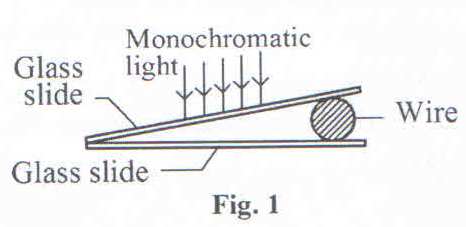
When the slides are illuminated with light of wavelength 500nm, 10 dark fringes are observed to occupy a distance of 2.5mm.
- Explain how the fringes are formed.
- Determine the diameter of the wire.
SECTION C
5.a) Define magnetic flux density.
b) Write an expression for the
- magnetic flux density B at a distance r from a long straight wire carrying a current I
- force F on a straight wire of length l carrying current I perpendicular to a uniform magnetic field of flux density B.
c) A moving-coil galvanometer consists of a rectangular coil of N turns each of area A suspended in a radial magnetic field of flux density B.
- Derive an expression for the torque on the coil when a current I passes through it.
- If the coil is suspended by a torsion wire for which the couple per unit twist is C, show that the instrument will have a linear scale.
- How can the current sensitivity of the instrument be measured?
d) Describe an experiment to determine the magnetic flux density of a uniform magnetic field using a search coil and a ballistic galvanometer.
e) Figure 2 shows an ampere balance. Wires AB and CD each of length 100cm,lie in the same vertical plane and are separated by 2.0mm.
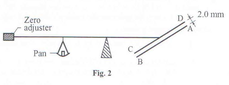
When a current I is passed in opposite directions through the wires,a mass of 0.3g is placed in the pan to obtain balance. Find the value of the current I.
6. a) In figure 3, X and Y are smooth conducting rails connected to a source of e.m.f, E. CD is a metal rod of length l m placed horizontally on X and Y perpendicular to magnetic field of flux density B.
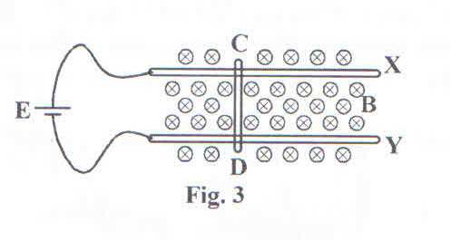
- Copy the diagram and indicate the direction of force F acting on the rod.
- Using the principle of conservation of energy, show that F = BIl, where I is current supplied by the source.
b) i) Describe the features of earth’s magnetic field.
ii) Sketch the resultant magnetic flux around a wire carrying current vertically upwards in the earth’s magnetic field.
c) A circular coil of 50 turns and radius 0.5m is placed with its plane perpendicular to earth’s magnetic meridian. It is connected to a ballistic galvanometer of sensitivity 5.7 ×10³ radC-1 and circuit resistance of 100Ω. When the coil is rotated through 1800 about a horizontal axis, the galvanometer deflects through 0.8 rads.
Calculate the
- horizontal component of earth’s magnetic flux density.
- p.d across a solenoid of 2000 turns per metreand resistance 5Ω that produces the same magnetic flux density as that calculated in (c) (i).
7.a) Define root mean square value of an alternating current.
b) i) Write down the expression for the e.m.f generated by a dynamo and use it to identify the factors which determine the maximum e.m.f.
ii) Explain the structural modifications needed to convert an a.c generator into a d.c generator.
c) An iron- cored coil having a low resistance and high inductance is connected in series with a filament lamp P. The coil and the lamp are then connected across a d.c supply as shown in figure 4.
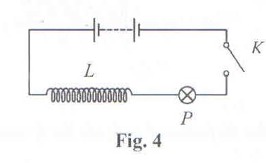
Explain what is observed when switch K is closed and then opened.
d) An alternating voltage V = V0 cos wt is connected across an inductor of inductance L.
- Derive the expression for the reactance of the inductor, XL.
- Sketch using the same axes the variation of applied voltage and current through the inductor with time.
e) Describe how a thermocouple ammeter is used to measure an alternating current.
SECTION D
8. a) i) State the law of conservation of current at a junction in an electric circuit.
ii) Explain why current from a battery is greater when bulbs are connected in parallel than when they are in serried across the battery.
b) A conductor of length l and cross sectional area A has n free electrons per unit volume. The average drift velocity of the electrons is v and each electron carries charge e.
Deriver an expression for the current which flows.
c) A battery with an e.m.f of 12 V and internal resistance 2 Ω is connected to a wire of resistance 10Ω.
- Calculate the p.d across the wire.
- What will the p.d across the wire become if a 15Ω resistor is connected in parallel with it?
d) i) Define electrical resistivity and state its unit.
ii) Describe an experiment to determine the resistivity of the material of a wire using an ammeter, a meter rule and voltmeter.
9. a) i) Define temperature coefficient of resistance and state its unit.
ii) Explain why temperature coefficient of resistance is positive for metals.
b) i) Derive the condition for balance of a metre bridge.
ii) Explain why the metre bridge is unsuitable for comparison of low resistances.
c) A standard resistors connected across the right hand gap of a meter bridge and a coil X across the left hand gap of the bridge. When the coil X is heated to a temperature of 400C, the balance length is 525mm from the left-hand end of the bridge. When the temperature of X is raised to 1000C, the balance point is 546mm from the left end.
- Calculate the temperature coefficient of resistance of coil X.
- Why are standard resistors made of alloys such as constantan and manganin?
10. a) Derive an expression for the energy stored in a capacitor of capacitance C, charged to a voltage V.
b) A parallel plate capacitor with plate area of 2×10⁻²m2 and plate separation of 5.0×10⁻³m is connected to a 500V supply.
- Calculate the energy stored in the capacitor.
- If the space between the plates is completely filled with oil and the total charge in the capacitor becomes 4.42 × 10⁻⁸C, find the dielectric constant of the oil.
c) Explain how a lightning conductor may protect a building from damage by lightning.
d) Describe an experiment to show that charge on a hollow conductor resides on the outer surface.